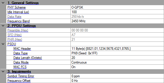
Click in the tree view to display the 802.15.4 O-QPSK BPSK setup. To learn about the frame structure and where these settings are applied within that structure, see the 802.15.4 O-QPSK BPSK concept topic.
Choices: O-QPSK | BPSK
Default: O-QPSK
Selects the 802.15.4 PHY scheme.
Range: 0–200000
Default: 100
Unit: us
Enter the idle interval in-between frames in seconds. The software accepts as many idle values as there are frames. When entering multiple idle values for a multi-frame setup, use a space or comma between values.
When idle interval is set to zero, a continuous waveform is generated. If there are more frames than values, the software restarts with the first value for the additional frames.
To determine how many frames are used in the signal, see the Number of Frames value in the Waveform Setup node.
Choices: 20 kb/s | 40 kb/s
Default: 20 kb/s
Selects the data rate for 802.15.4 BPSK PHY.
Choices: 100 kb/s | 250 kb/s
Default: 100 kb/s
Displays the data rate for 802.15.4 OQPSK PHY.
Choices: 780 MHz | 868 MHz | 915 MHz | 2450 MHz
Default: 2450 MHz
Select the frequency band for 802.15.4 OQPSK PHY. (See Table 66 in std 802.15.4-2011.) This parameter is not coupled with the Frequency setting under the Instrument node. Set an appropriate center frequency for the signal after selecting the band.
Whenever you change this setting, the Data Rate also changes according to Table 66.
Displays the Preamble field of PPDU in hexadecimal format.
Displays the SFD field of PPDU in hexadecimal format.
Displays the PHR field of PPDU in hexadecimal format. The value is automatically updated when the PSDU settings are changed.
These are the settings for the physical service data unit (PSDU) part of the frame that includes the payload data.
Click in the field, and then the dialog box icon  that appears to launch the MHR (MAC Header) - Hexadecimal Input dialog box. To use the dialog box, perform the following items as needed:
To enable the MAC header and to change values, click the MAC Header (hex) check box so that a check appears.
To disable the MAC Header,click the MAC Header (hex) so that the check box is unchecked.
For more information on the MAC header, refer to the IEEE standards 802.15.4.
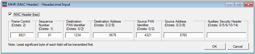
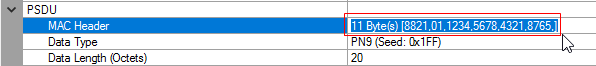
To configure this parameter using .NET API interface, specify the string in the same format, as shown in the GUI. For example, "11 Byte(s) [8821,01,1234,5678,4321,8765,]". To make sure the format is correct, you can highlight and copy the string directly from the parameter field in the GUI, as shown below.
Default: PN9 (Seed: 0x1FF)
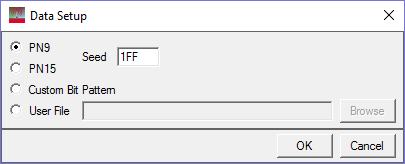
Click in the field, and then the dialog box icon that appears to launch the Data Setup dialog box. In the dialog box, select one of the following data types:
PN9
PN15
Custom Bit Pattern
User File
For PN9 and PN15 selections, the Seed field is active and available for use. However, it is inactive (grayed out) for the Custom Bit Pattern and User File selections.
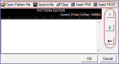
When you select Custom Bit Pattern, the PATTERN EDITOR provides controls (see figure below) for entering and editing data, including loading a previously saved pattern. In addition, there are 1 and 0 buttons for adding single bits. The keyboard may also be used to enter 1 and 0 values. The software remembers the current Custom Bit Pattern within a software session. That is, if another data type is selected and used, and then Custom Bit Pattern is reselected, the editor shows the previously entered custom pattern. If you click Clear, however, the custom pattern cannot be retrieved.
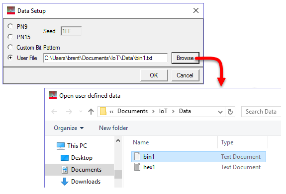
The User File selection lets you load a text file of either binary or hexadecimal data. Click Browse to open the "Open user defined data" window to select a file. The file path appears in the User File field.
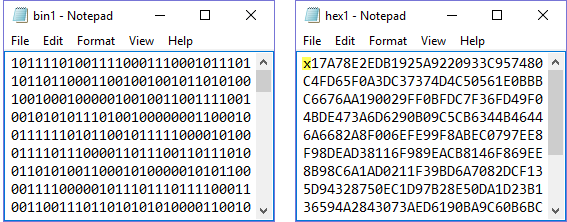
The software accepts two types of user data: binary and hexadecimal. The following figure shows an example of each data type. As shown, the hexadecimal data must begin with an 'x' to indicate hexadecimal data. The 'x' can be either upper or lower case.
Range: 0–127
Default: 20
Enter the length of MAC payload in octets. Use space to split different length between different frame, the number of space separated values should be less than or equal to the number of frames.
To determine how many frames are used in the signal, see the Number of Frames value in the Waveform Setup node.
Choices: Continuous | Truncated
Default: Continuous
For a multi-frame signal, select the mode that is applied to the MAC payload. If there is only one frame in the signal, then there is no difference in the choices
|
Continuous |
payload data bits are continuously distributed across multiple frames | |
|
Truncated |
payload data bits are the same for all frames, with the data size truncated for one frame |
Choices: On | Off
Default: On
Enable or disable the MAC FCS.
|
|
On |
|
data bits fill the FCS part per the IEEE 802.15.4 standards and adds two Octets to the frame length When there are multiple Data Length (Octets) values, the FCS octets are added to each of them. |
|
|
Off |
|
used to simulate an invalid FCS case and does not add any octets to the frame length |
Range: –300 to 300 ppm
Default: 0
Enter an error rate value that is used to shift the symbol rate. This error is added to the standard sample clock in the waveform header.
Range: –200 to 200 kHz
Default: 0
Enters an offset to the nominal carrier frequency in Hertz.